Flow mark injection molding are a common injection molding defect. While flow lines generally do not influence the structural integrity of the part, they can detract from its aesthetic quality. In this post, we’ll delve into the flow mark troubleshooting in injection molding, exploring their causes, and offering practical solutions to prevent them.
What are Injection Molding Flow Marks?
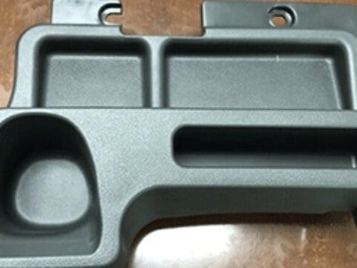
Flow marks, also known as flow lines, are visible streaks, ripples, or patterns that appear on the surface of injection-molded parts. They typically occur near the injection points or gates of the mold. While they generally don’t affect the structural integrity of the part, flow marks can degrade its aesthetic quality, especially in applications where surface appearance is critical. Additionally, they can provide insights into material flow behavior during the injection molding process.

Types of Injection Molding Flow Marks
- Concentric Flow Marks: Circular patterns around the injection point.
- Spiral Flow Marks: Spiral-shaped marks on the surface.
- Cloudy Flow Marks: Misty or cloudy patches on the part surface.
- Parallel Flow Marks: Regular, parallel streaks running along the surface.
- Shallow Flow Marks: Subtle, light lines or ripples.
- Raised Flow Marks: Bumpy, raised patterns on the surface.
- External vs. Internal Flow Marks: External marks are visible on the part’s surface, while internal marks appear in cross-sections.
What Causes of Flow Line in Injection Molding?
There are many reasons for flow mark in injection moulding, The following will show what causes flow lines in injection molding:
Material Causes
- Materials with a low melt flow index (MFl) are more viscous and resist flow, increasing the likelihood of flow marks. These materials cool more quickly and unevenly, leading to visible flow patterns.
- Inconsistent material temperature can cause certain areas to cool faster than others. If the material is too cold, it may not flow properly, resulting in visible patterns. Conversely, if it is too hot, the material may degrade, negatively affecting surface quality.
Machine Causes
- Low injection pressure can result in slow, uneven filling of the mold cavity. This leads to premature cooling and visible flow patterns.
- Slow injection speeds allow the material to cool too quickly at the mold walls. This creates a temperature gradient in the material flow, causing visible marks
- Insufficient nozzle and barrel temperatures can cause the material to cool prematurely. This affects the flow characteristics and can lead to visible patterns.
- Short residence times may not allow for proper material melting. Incorrect cycling times can affect material flow and cooling patterns.
Mold/Mold Design Causes
- Inadequate venting traps air in the mold cavity. This can cause uneven cooling and flow disruptions, leading to visible marks.
- Nonuniform wall thickness causes uneven cooling rates. This can result in visible flow patterns where thicker and thinner sections meet.
- Undersized gates or runners can restrict the flow of molten material, causing pressure drops and temperature variations.
- Poor gate placement can cause the mold cavity to fill unevenly, creating turbulence or weld lines. This often results in visible flow patterns that radiate from the gate area.
Temperature-related Issues
- A low mold temperature causes rapid surface solidification of the plastic. This creates a frozen layer that the subsequent material must flow over, leaving visible marks.
- Temperature differences within the mold or material can cause some areas to cool faster than others. This results in visible flow patterns where differently cooled areas meet.
Pressure-related Issues
- Low back pressure during screw recovery can lead to inconsistent melting and mixing of the material. This can result in flow marks due to temperature and viscosity variations in the melt.
- Insufficient holding pressure can allow the material to flow back slightly as it cools. This can exacerbate flow marks, especially near the gate areas.
How to Avoid Flow Mark in Injection Moulding?
Optimize Injection Pressure and Speed
- Increase Injection Pressure: Ensuring adequate injection pressure helps in achieving a uniform flow of molten plastic into the mold cavity. Low injection pressure can lead to slow and uneven filling, which causes flow marks.
- Optimize Injection Speed: A higher and consistent injection speed prevents the molten plastic from cooling prematurely as it flows into the mold. Slow injection speeds can cause the surface layer to solidify faster than the resin filling, leading to visible flow patterns.
Control Temperature Settings
- Melt Temperature: Maintain an optimal melt temperature to ensure that the plastic flows smoothly without cooling too quickly. Deviations from the recommended material temperature can disrupt flow uniformity and promote flow marks.
- Mold Temperature: Ensure the mold is heated to an appropriate temperature to prevent rapid surface solidification of the plastic. This helps in maintaining a uniform flow and reduces the risk of flow marks.
- Nozzle and Barrel Temperatures: Adjust the temperatures of the nozzle and barrel to ensure the plastic reaches the ideal melting state without cooling prematurely.
Adjust Back Pressure and Holding Pressure
- Increase Back Pressure: Enhancing back pressure during the injection process helps in better compaction of the molten plastic, pushing it evenly through the runners and molds.
- Increase Holding Pressure: Adequate holding pressure ensures that the material fills the mold cavity completely and uniformly, reducing the likelihood of flow marks.
Optimize Timing
- Dwell Time and Cycle Time: Adjusting the dwell time and cycle time ensures the plastic has fully melted and is adequately processed before injection. Proper timing helps in achieving uniform flow and cooling.
- Residence Time: Ensure sufficient residence time in the barrel to allow for proper melting of the plastic. Short residence times can lead to uneven melting and flow marks.
Improve Mold Design
- Uniform Wall Thickness: Design molds with consistent wall thickness to ensure even cooling rates across the part. Variations in wall thickness can cause differential cooling and flow marks.
- Proper Venting: Ensure adequate venting in the mold to prevent air entrapment, which can disrupt the flow of molten plastic and cause flow marks.
- Gate and Runner Design: Optimize the size and placement of gates and runners to facilitate smooth and consistent material flow. Small or thin gates/runners can restrict flow and lead to temperature drops, causing flow marks.
- Cold Slug Well: include a well-designed cold slug well to prevent flow disruptions and ensure a smooth flow of material.
Material Considerations
- Higher Melt Flow Index (MFl): Use plastic resins with a higher MFl, as they are less prone to uneven cooling and flow marks. These materials flow more easily and uniformly
- Consistent Material Temperature: Maintain a consistent material throughout the injection process to avoid premature cooling and uneven flow.
Quality Control Measures
- Regular Inspections: Conduct regular inspections of molds, machines, and processed parts to identify potential sources of flow marks and address them promptly.
- Advanced inspection Techniques: Use techniques such as surface profilometry or microscopy to quantify and analyze flow marks for process optimization.
Post-Molding Surface Treatment (Remedy for Flow Marks)
- Polishing or Bead Blasting: Use surface treatments such as polishing or bead blasting to smooth out the appearance of flow marks and improve part aesthetics.
- Coating: Applying a coating to the affected area can help mask the flow marks and restore a uniform surface finish.
Conclusion with Injection Molding Flow Lines
Flow marks affect the aesthetics of molded parts, and in some cases, can be accompanied by burn marks, further compromising the surface quality. By optimizing materials, mold design, and processing parameters, both flow marks and burn marks can be minimized, ensuring high-quality products. By selecting the right materials, optimizing mold design, adjusting processing parameters, and employing advanced monitoring techniques, Zhongde can significantly reduce the occurrence of flow marks, and prevent burn marks from occurring. Implementing these solutions ensures the production of high-quality, visually appealing, and structurally sound injection-molded parts.